QUESTION
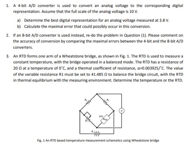
ANSWER
- The step size for given A/D converter is given as,
Δx= (Full scale value)/(2N)
=10/(24)
=0.625V
- Thus, number of steps needed=3.8/0.625
= 6.08
The integral value greater than 6.08 and nearest to it is 7
Now, (7)10 = (0111)2
Thus digital representation of 3.8 V is 0111.
- Maximum quantization error is given as,
Em= ±(Δx/2)
=±0.3125V
- The step size for given A/D converter is given as,
Δx= (Full scale value)/(2N)
=10/(28)
=0.0390625V
- Thus, number of steps needed=3.8/0.0390625
= 97.28
The integral value greater than 97.28 and nearest to it is 98
Now, (98)10 = (01100010)2
Thus digital representation of 3.8 V is 01100010.
- Maximum quantization error is given as,
Em= ±(Δx/2)
=±0.01953125V
Thus, we see that the maximum error in case of a 8 bit A/D converter is lesser as compared to that in case of a 4 bit A/D converter, i.e, the former is more accurate.
- The expression for the variation of resistance with respect to temperature is given as,
R = Ro(1+βΔT)
Where, R=measured resistance at given temperature
Ro= Resistance at reference temperature (generally 00C)
β= temperature coefficient of resistance
ΔT= change in temperature
Thus, for given case, 41.485=20(1+0.003925T)
i.e, T=273.690C
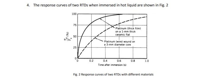
- The expression for variation of temperature of the RTD with time is given as,
Tm=To(1-e-t/Γ)
Where, Tm= measured temperature
To= reference temperature
t= given time
Γ=time constant
- For platinum thick film RTD, at t=0.2s, Tm/To=0.8125 (from response curve)
Thus, 0.8125= (1-e-0.2/Γ1)
i.e, Γ1= 0.119476s or 0.12s
Similarly for platinum wire wound RTD, at t=0.2s, Tm/To=0.375
Thus, 0.375= (1-e-0.2/Γ2)
i.e, Γ2= 0.42553s
- Generally, the reference temperature is 250C, if not mentioned specifically.
So, taking To=250C or 298K,
For platinum thick film RTD, Tm=298(1-e-8.37t)
And, for platinum wire wound RTD, Tm=298(1-e-2.35t)
- The matlab code written to plot the bode plot is:
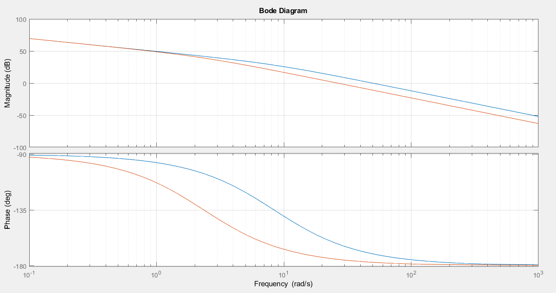
Bode plot for sys1, i.e, platinum thick film RTD is shown in blue colour, while that od sys2, i.e, platinum wire wound RTD in red.
Sys1 has a gain of -3dB at 54rad/s and sys2 has gain of -3dB at 32rad/s.
Thus bandwidth of sys1= 8.59Hz (converting rad/s to Hz) and that of sys2=5.093Hz
- Explained below:
- The pressure measured with respect to or relative to the atmospheric pressure is the Gauge Pressure.
The pressure exerted by the air weight present at the sea level is referred as the absolute atmospheric pressure.
The absolute pressure is equal to the sum of the atmospheric pressure and the gauge pressure.
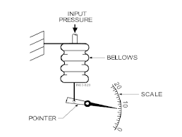
- Bellows give a measurement of the absolute pressure.
It is an arrangement of two springs below a metallic bar. The moving end of the spring is connected to the metallic assembly. As, the pressure on the mechanical assembly is varied, the spring either expands or contracts. This variation in pressure is reflected in terms of a moving pointer or an electrical signal. Phosphor Bronze, Brass, Beryllium Copper, Stainless Steel are normally used as the materials for bellows. The below diagram illustrates the same:
- The basic difference between laminar and turbulent flow of a fluid is on the basis of its velocity profile only.
In case of laminar flow, the velocity of the fluid at each and every point remains the same, the flow is smoother. Example- flow of water
In turbulent flow, the velocity of the fluid is different at different points and thus the flow isn’t smooth. Example- smoke out of a chimney
- Bernoulli’s effect is applicable to flow of liquids horizontally. It is based on the fact that the total pressure at any point in a liquid remains the same. Two types of pressure are mainly taken into consideration: the absolute pressure and pressure due to the flow of the liquid. Thus, an increase in the fluid velocity at a point will lead to decrease in the static or absolute pressure at that point. The mathematical equation depicting this is known as Bernoulli’s equation, given as:
P1 + 0.5ρV12 + ρgh1 = P2 + 0.5ρV22 + ρgh2
Here, Pk = Pressure at the kth location
Vk = velocity at kth location
Hk = height at kth location
Bernoulli’s effect is used basically for pressure and velocity measurement in fluids, if the pressure at one point is known, bernoulli’s equation (shown above) can be used to determine pressure at the other location. A few examples are: venturi meter, orifice meter, pilot tubes, etc.
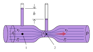
- Venturi meter is used for flow measurement in fluids. It is used for measuring horizontal flow rate in a fluid. It involves introducing an obstruction to the flow, by reducing the flow area. Thus there will be a reduction in velocity of fluid near the obstruction. So, according to the Bernoulli’s effect, there will be an increase in pressure. A manometer is used to measure this pressure difference. This pressure difference is represented as (P1- P2).
Now, as both the points are at the same height, thus the atmospheric pressure is same at both the initial point and the obstruction. Thus, the bernoulli’s equation reduces to:
(P1 – P2) = 0.5ρ( V22 – V12)
As V1 is known, V2 can be obtained by substituting the other values.
Fig: A venturi flow meter
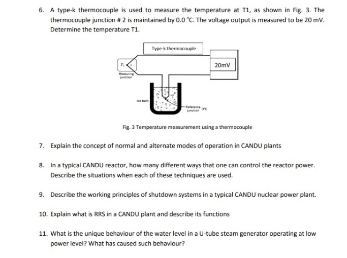
- We consider the seeback coefficient as K= 40µV/0C.
Thus, ΔT= ΔV/K
i.e, (T1- 0) = (20000µV)/( 40µV/0C)
T1 = 5000C
- CANDU or Canadian Deuterium Uranium, is a heavy water reactor used to generate electrical energy from nuclear energy. The name comes from the fact that, Deuterium Oxide (heavy water) is used as moderator in the process, while uranium is used as fuel.
The modes of operation are basically referring to the operation of control systems during different conditions.
When the plant is operating normally, i.e, no constrains, then this mode is the Normal Mode of Operation.
Alternate mode of operation is entered during low power demand. It may occur due to reasons like:
a) reactor tripping or setback,
b) there is low power demand
c) turbine or generator might have lost connection to the grid, or
d) uncontrolled steam pressure
- The various ways to control reactor power in a CANDU reactor are:
- Full Power Operation: Here, the power set-point and output is controlled by the governor operation. The extent of opening and closing of the governor will determine the steam output and thus the output power. The reactor power set-point is determined by the Demand Power Routine (DPR). This is done under normal operating conditions.
- Warm-up and Cool Down: This takes place if the plant has to be shut down and operated again. During warm-up, reactor power is adjusted up or down on the basis of steam pressure error. A steady state error of upto 5% is desired. Cool-down proceeds in much the same way, except that reactor power is not involved. The reactor is usually shut down when cool-down is initiated.
On decreasing reactor power, the transfer from the normal to the alternate mode takes place automatically when power drops below 2%.
- Low Power Operation: At very low power levels, the reactor power cannot be controlled just by varying the steam pressure. It is controlled by varying the plant loads by operating in the Alternate Mode.
- Manual Control of Reactor Power Set-point: This generally takes place during or after a setback and at very low power levels via controlling the steam pressure. Here the neutron power set-point is controlled by the operator in the alternate mode. He may raise or lower the flux set-point to a desired value at a desired rate.
- Manual Control of Turbine load: Here all other commands, other than turbine load control are deactivated. There is no effect on the normal operation. The reactor is made to follow the changes in the turbine load. If there is a reactor power setback the steam pressure controller will override the manual commands and lower turbine power as necessary to maintain steam pressure.
- CANDU plants have two shutdown systems, namely SDS1 and SDS2 incorporated within. Both of these are independent of each other and the reactor regulating system. They are functionally different, physically separate, and passive since the driving force for SDS1 is gravity and the driving force for SDS2 is stored energy. Both of these work together to shut down the plant immediately in case of occurrence of any hazardous situations.
The conditions which cause the shutdown systems to come into operation are:
- Loss of reactor regulation
- Loss of effectiveness of the primary heatsink.
SDS1 is designed to meet all the necessary safety conditions and also allow the reactor to be quickly restored to operational conditions within a time period of around 40 minutes. SDS2 is used as a backup for the case if SDS1 fails due to some unwanted factors. It is more extensive and would operate only if the operating period of SDS1 has elapsed.
- Reactor Regulating System (RRS) is a mechanism incorporated in CANDU plants to regulate the power output and reactor power set-points. All of these are affected by the conditions in which the plant is operating (low and high power demands, during and after setback, etc).
RRS is needed because of the following reasons:
- The set-point and rate of change of power has to be decided by the operator, which is needed to decide the mode of operation (normal or alternate mode of operation). Thus, there is automatic control of reactor power.
- Insertion or removal of control rods, to maintain the rate of reaction within controlled limits.
- Maintaining the neutron flux distribution close to its nominal design shape so that the reactor can operate at full power without violating bundle or channel power limits.
- To monitor various plant parameters for operation and safety purposes.
- In a U-tube steam generator, the primary water flows upwards through the tube first, making the bend and then flows back into the reactor coolant system piping.
On the secondary side, roughly a quarter of water, injected through the feedwater system, evaporates and the remaining water is circulated back into the boiling region. This makes the water level unique. All of this is caused by varying pressure differences in the tube.
Looking for best Engineering Assignment Help. Whatsapp us at +16469488918 or chat with our chat representative showing on lower right corner or order from here. You can also take help from our Live Assignment helper for any exam or live assignment related assistance